
2003 lincoln navigator radio wiring diagram harness of a 2005 ls market stereo due to thx bypass amp ford car audio 2004 air suspension factory s turn on wire i need for 2000 deck install 1988 tc installation 2001 town full 07 2007 navigation aftermarket repair parts and metra 70 5521 receiver dual f150 sony wires g35 fuse free. One trick that We use is to printing exactly the same wiring plan off twice.

34 2004 Lincoln Aviator Radio Wiring Diagram Gif In 2021 Lincoln Ls Lincoln Aviator Lincoln
YellowGreen Radio Ground Wire.

2005 lincoln ls radio wiring diagram. 2006 Lincoln Ls Radio Wiring Diagram wiring diagram is a simplified good enough pictorial representation of an electrical circuit. 2001 Lincoln LS V8. Aftermarket radio pioneer fh-x700bt.
2009 Lincoln Mark LT 2007 Lincoln. Find the Lincoln radio wiring diagram you need to install your car stereo and save time. Do you have a wiring diagram that gives the wire colors and pin numbers for the radio harness of a Lincoln LS - Answered by a verified Lincoln MechanicLincoln Town Car Wiring Electrical Diagram Shop Repair Service Manual EWD.
WhiteBlack Left Front Speaker Negative Wire -. A single trick that We 2 to print out a similar wiring. 2005 Lincoln Ls Wiring Diagram Manual Original.
2006 Lincoln Ls Radio Wiring Diagram. BlackGreen Stereo Antenna Trigger Wire. It shows the components of the circuit as simplified shapes and the capacity and signal contacts surrounded by the devices.
YellowRed Left Front Speaker Positive Wire. 2000 Lincoln Ls Radio Wiring Diagram wiring diagram is a simplified normal pictorial representation of an electrical circuit. Whether youre a novice Lincoln LS enthusiast an expert Lincoln LS mobile electronics installer or a Lincoln LS fan with a 2005 Lincoln LS a remote start wiring diagram can save yourself a lot of time.
In 1917 Henry Leland the founder of the Cadillac brand registered a new company Lincoln to begin production of aircraft power units commissioned by the United States military. 2000 lincoln 3 9 2000 ford explorer diagram 2005 lincoln aviator v8 diagram 2000 jeep grand cherokee diagram used 2000 lincoln ls v8 2000 saturn ls red car 2000 lincoln ls v8 issues images of lincoln ls green 19smystenimexde. By Admin December 10 2017.
September 7th 2013 No Comments Posted in Lincoln LS. When you use your finger or the actual circuit with your eyes it is easy to mistrace the circuit. 2005 Lincoln LS Stereo Wiring Information.
September 7th 2013 No Comments Posted in Lincoln LS. A wiring diagram usually gives guidance roughly. The automotive wiring harness in a 2005 Lincoln LS is becoming increasing more complicated and more difficult to identify.
Im upgrading the stereo and having trouble determining which wires are the VSS remote amp turn on and steering wheel volume controls. With precrimped ends and. Hello do you have a wiring diagram that gives the wire colors and pin numbers for the radio harness of a 2005 Lincoln LS standard stereo and also the wire colorspin numbers in the drivers kick panel.
Stereo Wiring Diagram. Lincoln LS 2005 Aftermarket Radio Wiring Harness with OEM Plug by Metra. 7th 2013 No Comments Posted in Lincoln LS.
2004 Lincoln Ls Stereo Wiring Diagram. Scroll down and find the Lincoln wire guide you need. 2002 lincoln ls 2004 installation parts radio wiring diagrams for 200 eclipse 5435 install market stereo due to harness of a 2005 diagram free 2001 alpine I Am Hooking Up An Aftermarket Cd Player In My 2002 Lincoln Ls Need To Know The Factory Color Scheme For Cars I.
I downloaded the wiring diagram from my alldata account but there are others diagrams that has different conections is this correct i dont want to blow it up. Radio Battery Constant 12v Wire. Presented here to help you understand the o2 sensor from an electronics and wiring diagram point of view.
Navigator 2005 Thx Bypass Amp Ford Truck Enthusiasts Forums. September 7th 2013 No Comments Posted in Lincoln LS. When you employ your finger or perhaps stick to the circuit together with your eyes its easy to mistrace the circuit.
It shows the components of the circuit as simplified shapes and the capacity and signal contacts together with the devices. Ensures dependable connection Superior product quality. 2005 Lincoln LS 2004 Lincoln LS 2003 Lincoln LS 2002 Lincoln LS 2001 Lincoln LS 2000 Lincoln LS.
The attached one is from alldata. For example when a module is powered up and it sends out a signal of 50 percent the voltage plus the technician would not know this he would think he has a problem as this individual would expect a. A wiring diagram usually gives guidance just about the relative slant and settlement of.
Print the electrical wiring diagram off plus use highlighters to trace the signal. Whether your an expert Lincoln Town Car mobile electronics installer Lincoln Town Car fanatic or a novice Lincoln Town Car enthusiast with a Lincoln. Looks like the 16 pin connector has the audio signalsIm confused.
OrangeBlack Radio Accessory Switched 12v Wire. 2005 town car wiring diagrams written for lincoln dealership mechanics this factory published original wiring diagram shows you how to follow the wiring from bumper to bumper. Lincoln LS 2005 Aftermarket Radio Wiring Harness by American International with OEM Plug and Amplifier Integration.
American International Installer Preferred wire harnesses are a vital link between todays mobile electronics and a. 2000 Lincoln Ls V8 Radio Installation Diagram. LINCOLN Car Manuals PDF.
GrayBlack Right Front Speaker Positive Wire. Metra preassembled wiring harnesses can make your car stereo installation seamless or at least a lot simpler. Print the cabling diagram off in addition to use highlighters in order to trace the circuit.
Diagram 95 lincoln stereo wiring full version hd quality devdiagram aitrearchivenezia it do you have a that gives the wire colors and pin numbers for radio harness of 2005 ls 2004 navi problems installing after market due to help vs cadillac forums installation.
2005 Lincoln Ls Radio Wiring Diagram. There are any 2005 Lincoln Ls Radio Wiring Diagram in here.
The system is a double articulating overlapping type in which the blades park under a concealing vacuum operated lid. Where are all the fuselinks located on a 1969 corvette.

Dqsi2aspci2v2m
Download chevy corvette 1954 1956 wiring diagram.
1969 corvette wiper motor wiring diagram. Grounding is problematic on a fiberglass bodied vehicle. The wipers work great high low and. Chevrolet corvette 2014 fuse box diagram.
There are a few simple test you perform to diagnose problems with your windshield wiper motor. If you want to find the other picture or article about 73 corvette. My Corvette Wiper Motor Quit Can you help me 1969-1972.
If the 1991 is anything like th 1969 to 1982 the ground is open under the dash at the wiper switch. A wiring diagram is a streamlined conventional pictorial depiction of an electric circuit. A small strong fl ashlight helps you see wires and connectors that are.
1977 1982 Corvette Corvette Spark Plug Wire Route Corvette Corvette Engine Corvette Art. 1977 corvette wiper motor wiring diagram 1977 corvette blower motor wiring diagram. Wiper Motor Wiring Diagram Together With 1967 El.
Wiper Wire Schematic in color with help test. 1969 Corvette Wiper Motor Wiring Diagram. 1969 corvette color wiring diagram 11 c3 pdf docrebuild s oosoez guides wiper vwd6900 lectric limited of a 1970 bb cpe 69 vette 1968 heater and air laminated chassis 71 chevelle door ajar switch repair installation help from wire schematic tracer ebook databases coil resistor 1972 chevy c4 jul 57 65 diagrams electrical 1982 1957 will 1979 corvetteforum 1991 engine.
There is one fuse block in the engine compartment on the passenger side of the vehicle. The fuse box on a 1985 corvette is located on the side panel of the dash on the passenger side. A help section for your motor will be available soon.
Each part should be placed and connected with other parts in particular way. My Corvette Wiper motor stopped working how can I test it. 57 65 Chevy Wiring Diagrams.
Radiator hoses 19931994 exploded view 1969 69 corvette wiper motor wiring diagram mar 21 2019 amp horbar many thanks for visiting at this website listed below is a excellent image for 69 corvette wiper motor wiring diagram we have been searching for. This bulletin is being published as an aid to understand and to easily diagnose 1968 Corvette windshield wiper system. Wipers only work on occasion.
It also helped me determine the correct function of the relay since mine is broken. You are right below. Appliances published on 08 jun 2014 1969 corvette wiper wiring diagram free corvette wiring diagrams jeep grand cherokee fuse box diagram 1968 chevelle wiring diagram wiper motor wiring diagram 1969 camaro dash 1969 73 chevrolet corvette with factory air first followed by the wiring evaporator and finally the control panel cover wiring.
Do not use this for 1968 cars. Open the passanger right side door. Willcox testing a 1969-1976 Wiper motor and some brief help on how to repair a relay.
The Willcox Corvette video Willcox Corvette Bench Testing a 1969-1972 Corvette Wiper Motor was a HUGE help in determining what ground signals control different functions of the wiper motor. Windshield Wiper Motor Wiring Diagram 1969 camaro windshield wiper motor wiring diagram 1969 corvette windshield wiper motor wiring diagram afi windshield wiper motor wiring diagram Every electrical arrangement consists of various different parts. The most sage advice is not really only look from the diagram nevertheless understand how the constituents operate when in use.
Free Picture Well Rh Flyvpn Co 70. 1969 corvette color wiring diagram 11 69 vette c3 pdf 1970 wire vwd6900 lectric limited of a bb cpe 1957 will electronic ignition 73 c4 jul laminated chassis 1979 corvetteforum for 77 64 cj5 full chevelle ac 1968 mustang schematic tracer 1977 wiper motor vwd8200 starter id 1985 headlight chevy nova harness camaro vwd5557 light factory diagrams. If not the structure wont function as it ought to be.
1969-1972 Corvette Windshield Wiper Motor Tech Help Wire Schematic With Test. I have a 1969 Corvette with a correct Windshield wiper Motor wiring harness new vacuum hoses new safety valve by the windshield wiper new actuator and good vacuum. The only component that is not new is the Windshield wiper door vacuum control solenoid switch that is connected at the back end of the tach.
20130 Direct Fit 1970-72 ChevelleMalibu. 1977 1982 Corvette Wire Schematic Courtesy Lamp 77 82 In General Corvette Ls Engine Swap Corvette C3. 1970 Corvette Wire Schematic Tracer Will Inc.
The wiring diagrams for this year indicate that red is high speed and green is low speed. As a result the 62-liter engine will produce 766 horses and accelerate to. Below you will find simple suggestions combined with a wiring.
Yes with a few simple tests you can tell if the problem is from the wiper motor wiring or switches. Hope this is of help. Following diagrams is pretty simple but making use of it inside the opportunity of how the machine operates is a new different matter.
1969 Corvette Wiper Motor Wiring Diagram Source. 1969 Corvette Windshield Wiper Vacuum Diagram Wiring 1972 Firebird Wiper Motor Wiring Diagram Jimnys Tehsusu Decorresine It. The wiper motor is electric and the lid is vacuum operated.
1969 Corvette Wiring Diagram Free 2006 Ford F350 Fuse For Schematics. If You Have Apr 13th 2021. Check for the ground at the wiper motor when the wipers decide not to work.
For example when a module will be powered up and it also sends out the signal of 50 percent the voltage in addition to the technician will not know this he would think he has a challenge. Instrument panel fuse block. Chevrolet corvette 1970 wiper motor schematic diagram circuit and wiring diagram download for automotive car motorcycle truck audio radio electronic devices home and house appliances published on 12 jun 2014.
Effectively read a wiring diagram one provides to find out how typically the components in the system operate.
1969 Corvette Wiper Motor Wiring Diagram. There are any 1969 Corvette Wiper Motor Wiring Diagram in here.
1984 ford f 150 wiring diagram alternator. 1984 ford f 150 wiring diagram alternator and and plugins.

1985 F250 5 8l Wiring Diagrams And Fuse Box Diagram Ford Truck Enthusiasts Forums Ford Truck Ford F350 Ford F150
A wiring diagram is a streamlined traditional photographic representation of an electric circuit.

1980 ford f150 alternator wiring diagram. Ad Online Chat Support. Ford 3G Alternator wiring - Figure A. Generator to Alternator conversion diagram and Tec tips.
You Dont Need Drawers Packed with Outdated Manuals. This is the original wiring diagram printed by Ford for dealer mechanics. Ad Discover 500000 Wiring Diagrams for Vehicles.
All the top makes. They are PDFs and you can zoom in on them to a great extent in order to actually use them. READ 87 Ford Ranger Wiring Diagram Images.
Alternator Voltage Regulator Instrument Panel Starter and Drive Distributor Distributor Modulator System. We also have some more images connected to motorola alternator regulator wiring diagram please see the pic gallery below. This is the diagram of every components in the alternator.
Typical relay wiring diagram Figure C. Many thanks for visiting here. Some of these service operations require the use of tools specially designed.
1980 Ford Truck Wiring Diagram Charging 1984 ford f 150 wiring diagram alternator and and plugins 1980 86 ford f series stereo wiring identification for install all old ford truck owners need to know ignition control module from 85 ford f150 charging system diagram the. Ford 3 Wire Alternator Wiring Diagram. Circuit Wiring in 1983 Ford F150 Wiring Diagram image size 626 X 732 px and to view image details please click the image.
It will help you to understand connector configurations and locate identify circuits relays and grounds. Repair Manuals Service Manuals Workshop Manuals ECP Diagnostics. A single trick that I actually 2 to print out the same wiring plan off twice.
Assortment of 1987 ford f150 wiring diagram. 0A-3-Vehicle Identification Number. Free Download with 1983 Ford F150 Wiring Diagram image size 1003 X 701 px and to view image details please click the image.
When you employ your finger or the actual circuit along with your eyes it is easy to mistrace the circuit. Although the schematic is in black and white the color of each wire. Try eManual Online Instead.
Ad Discover 500000 Wiring Diagrams for Vehicles. Print the electrical wiring diagram off in addition to use highlighters to be able to trace the signal. Wiring diagrams for 1980 trucks are contained in a separate Wiring.
Try eManual Online Instead. Print the cabling diagram off and use highlighters to be able to trace the routine. Or better yet click the pop-out icon shown to the right and available at the upper right corner of the page.
You Dont Need Drawers Packed with Outdated Manuals. All the top makes. Generator wiring 1964-12 and Alternator wiring 1965 and up.
Right Hand Side of Cylinder Block at Rear of Distributor. The best method to. Searching for details about ford alternator wiring diagram late model 302.
When you use your finger or follow the circuit together with your eyes it may be easy to mistrace the circuit. 1983 Ford F150 Alternator Wiring Diagram. Typical relay pin-out diagram Figure D.
Ford 6g Alternator Wire Diagram Wiring B89 Justice. 1980 Ford F150 Wiring Diagram. Ford 302 alternator wiring diagram.
Ford 1-G alternator wiring - Figure A. It is a diagram for the alternator in a Ford Focus see also Ford Focus Repair Manual Ford Escort Ford F-100 Ford Taurus Ford Mustang Ford Model T Ford GT40 Ford Thunderbird Ford Shelby Cobra and other Ford cars that use the similar alternator. You are right below.
1989 Ford F 150 Alternator Wiring Diagram 45 77 197 80. Instant workshop manual download. Diagram Radio Wiring For 89 F150 Full Version Hd Quality Mediagrame Arteramo It.
Ad Online Chat Support. It is the same for Ford F150 F250 and other Ford F-Series cars. Ford Alternator Wiring Diagram.
1983 Ford F150 Radio Wiring Diagram On 1983 Images. 1 trick that I actually 2 to printing the same wiring. 1980 1986 bullnose f100 f150 larger f series trucks wiring diagram for 1987 ford truck rewiring so motor will start.
Repair Manuals Service Manuals Workshop Manuals ECP Diagnostics. Diagram Ford F 350 Alternator Wiring Full Version Hd Quality Pindiagram Mbreporter It. Voltage regulator - Ford Drawing A.
Instant workshop manual download. Transmission Regulated Spark System Headlamp Parking Lamp Taillamps Dome Lamp Mirror Lights Camper Wiring Windshield Wiper Motor. You can follow the wiring in your truck from bumper-to-bumper.
Sometimes even if you shut away from power some electrical wiring may be connected in order to another circuit and hence may still pose a danger of electric surprise. These are Fords wiring diagrams also known as schematics for the 1980 - 86 light trucks.
1980 Ford F150 Alternator Wiring Diagram. There are any 1980 Ford F150 Alternator Wiring Diagram in here.
Oldsmobile Radio Stereo Wiring Diagrams. Find the Oldsmobile radio wiring diagram you need to install your car stereo and save time.
Gm Cutlass Rwd 1970 1987 Wiring Diagrams Repair Guide Autozone
Chassis wiring 1973 Cutlass.
1983 cutlass supreme wiring diagram. All major topics are covered including complete step-by-step instructions diagrams illustrations wiring schematics and specifications to repair and troubleshoot. Chassis wiring 1970-72 Cutlass continued. In the trunk on the drivers side is an electrical disconnect.
Please copy and paste the link below instead. Many of those cars used aluminum wire which were prone to corrode. Engine and Chassis wiring 1970-72 Cutlass.
Inlet hose is warm return hose is not. 1994 OLDSMOBILE 98 4DR SEDAN wiring information. With 2 Spade Rectangle Connector.
Oldsmobile Cutlass Cutlass Salon Cutlass Supreme with A6 Compressor with R4 Compressor 1977 AC Compressor Wiring Harness by Four Seasons. What color diagram for 1983 oldsmobile cutlass supreme brougham the ground wire what color are the the battery and the ground because the ground wire not black Read full answer Be the first to answer Apr 30 2014 1983 Oldsmobile Cutlass Supreme. 1981 1987 cutlass supreme car radio stereo wiring diagr try each one with the key off to see if either has power and then turn your key to accessory and see which one has power.
Fuse box diagram Oldsmobile Cutlass fuse box diagram. 1987 Cutlas Supreme Wiring Diagram. Scroll down and find the Oldsmobile wire guide you need.
88 OLDSMOBILE DELTA 1985 2DR SEDAN wiring information. Whether your an expert installer or a novice enthusiast with a 1987 oldsmobile cutlass supreme an automotive wiring diagram. Whether your an expert installer or a novice enthusiast with a 1987 Oldsmobile Cutlass Supreme an automotive wiring diagram can save yourself time and headaches.
1994 OLDSMOBILE BRAVADA 4DR SUV wiring information. 1983 Oldsmobile Cutlass Supreme Sedan LS Turbo Build. Ignition Switch Harness or Use Hot Side of Brake.
Access our free Wiring Diagrams Repair Guide for GM Cutlass RWD 1970-1987 through AutoZone Rewards. Engine and Chassis wiring 1973 Cutlass. Wiring diagram for a cutless supreme 1987 just want to know the wiring diagram on motorer.
Back in the game after 10 years. 1984-87 Oldsmobile Cutlass Supreme Cruise Control Information 1984-87 Oldsmobile Cutlass Supreme Cruise Control Wiring Information. Asked by Carol-lynn Jul 14 2014 at 1008 PM about the 1987 Oldsmobile Cutlass Supreme.
CIERA OLDSMOBILE CUTLASS 1991 4DR SEDAN wiring information. Lots of pics 1978 cutlass supreme front grille ans front lights bezels. In many cases this type of book can be used in place of a wiring diagram--and may have been by the factory.
Oldsmobile Cutlass 1978 1981 fuse box diagram. Just want to know the wiring diagram on motorer. This book covers all 1983 Oldsmobile models including Firenza Omega Cutlass Ciera Cutlass Delta 88 Custom Cruiser Ninety-Eight Toronado.
We have 10 images about 1983 cutlass fuse box manual 1983 cutlass fuse box instruction manuals 1983 cutlass fuse box user manuals service manual 1983 cutlass fuse box pdf download user guides. If you are looking for 1983 cutlass fuse box youve come to the right place. Oldsmobile Cutlass Ciera.
1994 OLDSMOBILE ACHIEVA 4DR SEDAN wiring information. One of the most time consuming tasks with installing a car stereo car radio car speakers car amplifier car navigation or any mobile electronics is identifying the correct wires for a 1987 Oldsmobile Cutlass Supreme. Not only 1983 cutlass fuse box you could If you are looking for 1983 cutlass fuse box youve come to the right place.
1981- 1987 Cutlass Supreme Car Radio Stereo Wiring Diagr Try each one with the key off to see if either has power and then turn your key to accessory and see which one has power. With this manual on hand you will have 100 confidence to do a repair or service your own vehicle. Oldsmobile Cutlass Supreme Wiring Diagram Wiring Diagram.
Gm cutlass rwd 1970 1987 repair guide. Get a really good look at the wires going to this plug. Wiring diagram for a cutless supreme 1987.
1978 1979 1980 1981. Make sure your doors are closed though cause orange is also the wire for interior lights and cigarette lighter which is hot all the time. Having a Oldsmobile stereo wiring diagram makes installing a car radio easy.
Factory workshop repair manual for the 1983 Oldsmobile Cutlass Supreme. 1994 OLDSMOBILE 88 4DR SEDAN wiring information. Products are engineered and tested to provide years of.
Oldsmobile Eighty Eight 88.
1983 Cutlass Supreme Wiring Diagram. There are any 1983 Cutlass Supreme Wiring Diagram in here.
This is the same manual that technicians use to fix your machines. Wiring Diagram Generator Avr Unique Wiring Diagram.

Harley Davidson Wiring Diagram Agnitum Me And At Harley Wiring Diagram In 2021 Pocket Bike Home Electrical Wiring Diagram
Get your eManual now.

Airman generator wiring diagram. All methods use an Automatic Voltage Regulator AVR to supply DC output to the exciter stator. The exciter rotor AC output is rectified to a DC input for the main generator rotor. Portable Generator MMD Equipment AirMan SDG125S-6A6 Instructional Manual.
In order to use a machine safely people with sufficient knowledge and. This is a very comprehensive manual DOWNLOAD in PDF format for AIRMAN HOKUETSU 8B 6A SERIES ENGINE GENERATOR Features detailed exploded views. AIRMAN AX05 Excavator Parts Catalog.
DCA45USI ECU-EGS Engine Wiring Diagram. The generator is made up of seven. Table of Contents 1.
Engine Wiring Diagram 9. Our Airman Excavators workshop manuals contain in-depth maintenance service and repair information. This manual explains and illustrates proper handling of the unit method of daily inspection and maintenance to enhance the performance of AIRMANs generators.
DCA60SSI2 Generator and Engine Wiring Diagram. ELECTRIC START INVERTER PORTABLE GENERATOR CARB AND CETL. DCA45USI ECU Wiring Diagram.
100 copper wound brushless design for years of long lasting power. Remove the assembly level plates and place the cushion rubbers in their respective places on the frame. Aalsmeerderdijk 156 1438 AX Oude Meer The Netherlands Tel.
Wiring Diagram SDG45S-6A665S-6A6 Terminal plate Voltage selector sw. Airmar Wiring Diagram Garmin P66 600w SDT Best Deal Blue Bottle Marine. Titan 8500 Generator Wiring Diagram Best Of Titan Generator Wiring.
Permanent Magnet Generator PMG Auxiliary Winding AUX. Wiring Diagram 92 Engine Wiring Diagram SDG25S-6A7 A040580. Infohokuetsunl AIRMAN USA CORPORATION 7633 Adairsville Hwy AdairsvilleGA 30103 Tel.
Please see the Home Page with explanation how to order and receive Manuals and Code Books. Welding Generator Output Change CC power Eco Welding Rod Diameter in 564 - 316 Rated Frequency Hz 60 Rated Speed rpm 3600 Phase 1-Phase 1-Phase 3-Phase Rated Voltage V 120 240 480 Power Factor 10 10 08 AC Generator Rated. DCA70SSIU2 Generator and Engine Wiring Diagram.
121 High Hill Road Swedesboro NJ 08085 Tel. 1-770-769-4335 ENGINE GENERATOR SDG series Engine GENERATOR 105800kVA SDG series. Airbus abbreviations a320 aircraft free ebook download as pdf file pdf text file txt or read book online for free.
The airman generator service manual Documents at ebooksquad we provide free pdf file. Tutorial manual guide and more. Mobile generators 67 pages.
Wiring diagram airman generator. Stamford Generator Windings Wiring Diagram Wiring Diagram. View online or download mmd equipment airman sdg150s 6a6 service manual instructional manual.
DCA45USI W EGSKey Engine Wiring Diagram. Airman AX50U-4 parts manuals. Each method has its individual advantages.
Electrical Parts Generator Wiring Diagram Molded case circuit breaker SDG25S -6A7 three-phase. 25 rows Airman SDG25S-8A7 engine generator Spare Parts Catalog. Generator Wiring Diagram 3.
Wiring Diagram SDG100S-6A6 Terminal plate To Battery To Monitor lamp ACGenerator A040658. Mmd equipment airman sdg150s 6a6 pdf user manuals. More advanced systems use an additional input to the AVR.
Airman AX50U-4 manual collection3 manuals. To Battery To Monitor lamp ACGenerator A040166. DCA70SSIU Generator and Engine Wiring Diagram.
DCA60SSAI Generator and Engine Wiring Diagram. Insert or place adjusting shims on the vibration isolator rubber of both engine and generator main unit 7. PDF Spare parts Catalogs Service and Operation Manuals.
16 Excavators Airman Service Repair Workshop Manuals. 118 corometrics schematics 1995 mercruiser 350 wiring diagram 2012 air force promotion outlook android hacking app for pot of gold slot machines answers of kangaroo. Place the engine with the generator main unit on the cushion rubbers and fasten it with nuts.
Airman Generator Wiring Diagram. There are any Airman Generator Wiring Diagram in here.
You Dont Need Drawers Packed with Outdated Manuals. All the top makes.

1998 F150 4 6l Firewall Mounted Solenoid Relay F150 Ford F150 Relay
A wiring diagram is a streamlined conventional photographic representation of an electric circuit.

2000 ford expedition starter wiring diagram. BlackGreen Vehicle Second Ignition Wire Location. NA Car Stereo Antenna Trigger Wire. It shows the components of the circuit as simplified shapes and the capability and signal friends amongst the devices.
1 trick that We use is to printing the same wiring picture off twice. Variety of 2000 ford f150 starter solenoid wiring diagram. Ad Discover 500000 Wiring Diagrams for Vehicles.
BlackGreen Car Radio Illumination Wire. You Dont Need Drawers Packed with Outdated Manuals. Vehicle Battery Positive Wire.
Ad Find Ford Wiring Diagrams. The wire from the. Instant workshop manual download.
For instance if a module is usually powered up also it sends out a new signal of fifty percent the voltage and the technician will not know this he would think he provides a challenge as he would expect a 12V signal. Try eManual Online Instead. Sometimes its simple and sometimes not.
2000 Ford Super Duty Wiring Diagram Save Diagrams Accident Ford F 150 How To Replace Starter Trucks Diagram 1999 Ford Expedition Starter Wiring Full Version Hd Quality. Repair Manuals Service Manuals Workshop Manuals ECP Diagnostics. Ad Discover 500000 Wiring Diagrams for Vehicles.
The other terminal is not used most of the time. NA Car Stereo Amp Trigger Wire. Ford Orion 1990-1999 Electrical Wiring Diagrampdf.
Ford Sierra Wiring Diagrampdf. When you employ your finger or perhaps the actual circuit along with your eyes it is easy to mistrace the circuit. To wire a 12 volt starter solenoid first disconnect the black negative cable from the vehicles battery and then connect the red battery cable to the large bolt on the solenoid.
Try eManual Online Instead. 2000 F150 Starter Wiring Diagram wiring diagram is a simplified adequate pictorial representation of an electrical circuit. 2000 Ford Expedition Car Radio Wiring Diagram Car Radio Battery Constant 12v Wire.
The by yourself excuse it. The small wire with 90end goes to sol. GreenPurple Vehicle Battery Positive Wire Location.
Ford S-MAX 2006 Electrical Wiring Diagramrar. It shows the components of the circuit as streamlined shapes and also the power and signal links in between the devices. Print the wiring diagram off in addition to use highlighters in order to trace the routine.
Vehicle Ignition Wire. Dont have a wiring diagram for you but ill try to explain. BlueGreen Vehicle Ignition Wire Location.
Starting with heavy gage cables---one goes to battery positive--the other heavy cable goes to starter bolt on back of bendix or 38 stud with nut. It shows the components of the circuit as simplified shapes and the facility and signal links amid the devices. Terminal mark I thats ign.
Blue Car Stereo Amplifier Location. 2000 Ford Expedition Car Start Wiring Diagram. BlackPink Car Radio Ground Wire.
WhitePurple Car Radio Accessory Switched 12v Wire. Ford Starter solenoid Wiring Diagram wiring diagram is a simplified normal pictorial representation of an electrical circuit. 2000 Ford F150 Starter Solenoid Wiring Diagram Effectively read a wiring diagram one provides to know how the components in the program operate.
Diagram Stereo Wiring For 1998 Ford Expedition Full Version Hd Quality Piediagram Mbreporter It 2000 Ford Expedition Crank I Replaced The Starter Solenoid Headlight Wiring 2004 Ford Expedition Lincoln Navigator. 2000 Ford Expedition Wiring Diagram. Ford f250 starter solenoid wiring diagram new dual battery diagrams.
2000 Ford F150 Starter Solenoid Wiring Diagram Print the cabling diagram off plus use highlighters to trace the routine. Heres what to doFirst you compulsion to acquire the old-fashioned starter out. Ad Online Chat Support.
BlueBlack Car Stereo Dimmer Wire. Vehicle Second Ignition Wire. Side comming from ign.
When you employ your finger or perhaps follow the circuit along with your eyes it is easy to mistrace the circuit. For instance when a module is powered up and it also sends out a signal of fifty percent the voltage and the technician would not know this hed think he offers a problem as he or she would expect the 12V signal. May 20 2020 - 35 Best Of 2000 ford Expedition Starter Wiring Diagram- Your starter went out and you want to replace it.
2000 Ford Expedition Starter Wiring Diagram. There are any 2000 Ford Expedition Starter Wiring Diagram in here.
Please be sure to test all of your wires with a digital multimeter before making any connections. 2001 Gmc Sonoma Wiring Manual Pdf PDF Online.
Radio Wiring I Need The Radio Wiring Diagram For A 2001 Chevy
Having big electrical problem and i need a place to start can you send me a copy.
2001 gmc sonoma radio wiring diagram. Gray Car Stereo Dimmer Wire. Diagram 2001 Gmc Sonoma Wiring Full Version Hd Quality Mmcdiagram Amicideidisabilionlus It Diagram 2002 Gmc Sonoma Rear Tail Light Wiring Full Version Hd Quality Diagramrt Teatrodelloppresso It Diagram 93 Sonoma Radio Wiring Picture Full Version Hd Quality Cpudiagram Amicideidisabilionlus It. I have the complete wire schematics for 2001 gmc sonama both engines all options everything pdf file.
Yellow Car Radio Ground Wire. When you make use of your finger or even the actual circuit along with your eyes it may be easy to mistrace the circuit. Then a rubber hose about 125 outside diameter is clamped to the front of each check valve and connects to the air pump which is hidden behind the vehicles grille in front of the radiator.
For instance in case a module is usually powered up also it sends out a signal of fifty percent the voltage plus the technician will not know this he would think he has an issue as he would expect a 12V signal. Diagram Ford Courier Wiring Full Version Hd Quality Gwendiagram Arteramo It. 2001 GMC Sonoma Car Stereo Wiring Diagram.
These GMC Wiring information Aftermarket AutostartAlarm Technical Wiring Diagrams are very useful if not required for the installation of alarms autostart alarms remote starts doorlock info and any other aftermarket installation that would require you to know the Wire Information Wiring Information of your GMC. Brown Car Stereo Antenna Trigger Wire. 93 sonoma radio wiring diagram picture 2003 gmc full 2000 for a 2001 chevy 1994 1999 diagrams repair guide vehicle is sls 4wd i changed the in me 1998 s 55 luxury 2004 yukon bose gm.
If you have not had time to read this 2001 Gmc Sonoma Wiring Manual Pdf PDF Kindle then you suffered heavy losses but quiet on. More information on using a multimeter and testing wires. 1998 Gmc Sonoma Engine Diagram Auto Wiring Diagrams Advice.
Then the speaker wires are all the same as the other diagrams I looked at. 2001 Gmc Jimmy Wiring Harness Diagram B76 Threat. Pink Car Stereo Amp Trigger Wire.
On the 2001 gmc jimmy 43L v6 engine there are two air pump check valves. Good means the same to me. Listed below is the vehicle specific wiring diagram for your car alarm remote starter or keyless entry installation into your 1998-2003 Gmc Sonoma.
Black Car Radio Illumination Wire. 2001 Gmc Jimmy Stereo Wiring Diagram Diagrams Quality Good. Diagram Truck Wiring 99 Sonoma Full Version Hd Quality Diagramatica Lavocedelmare It.
Gmc Stereo Wiring Diagram. This information outlines the wires location color and polarity to help you identify the proper connection spots in the vehicle. Read wiring diagrams from negative to positive in addition to redraw the signal like a straight range.
2002 ford mustang wiring diagram 98 gmc wiring schematic 1996 gmc sonoma wiring diagram gmc wiring schematics 2002 gmc sierra 2500hd wiring diagram 2001 gmc jimmy stereo wiring diagram 2001 gmc wiring diagrams 1998 gmc jimmy trailer wiring diagram 112feuerwehr-randeggde. Yellow and brown light blue and dark blue light green and dark green tan and gray but none have the thin orange wire. When you use your finger or perhaps stick to the circuit along with your eyes its easy to mistrace the circuit.
GMC wiring colors and locations for car alarms remote starters car stereos cruise controls and mobile navigation systems. 2001 Gmc Sierra Wiring Diagrams Auto Organisation. Orange Car Radio Accessory Switched 12v Wire.
1 trick that I use is to printing exactly the same wiring diagram off twice. READ 2001 Gmc Sonoma Radio Wiring Diagram Images. 2002 Gmc Sonoma Radio Wiring Diagram Effectively read a cabling diagram one provides to learn how typically the components in the system operate.
Car Radio Battery Constant 12v Wire. 2001 Gmc Sonoma Radio Wiring Diagram Print the electrical wiring diagram off and use highlighters in order to trace the signal. It has a thick orange wire red wire thin orange wire and a blackwhite ground wire.
2002 Gmc Jimmy Wiring Diagram. If you like to read 2001 Gmc Sonoma Wiring Manual Pdf PDF Online. If anyone need it quo.
I Have A 2000 Gmc Sonoma Suddenly Lost The Voltage To Sdometer Tachometer Door Locks Radio Dome Lights And. All circuits are usually the same voltage ground single component and changes. 2001 Gmc Sonoma Wiring Diagram Print the wiring diagram off in addition to use highlighters to trace the routine.
Man is really appriciate a schematic right now. The check valves are screwed onto those pipes. NA Car Stereo Amplifier Location.
Theres a pipe about 1 diameter that comes off each of the exhaust manifolds. Did you also know that 2001 Gmc Sonoma Wiring Manual Pdf PDF Download is the best sellers book of the year. Diagram Wiring Harness For 2001 Gmc Sonoma Full Version Hd Quality Rediagram Festivalsportintegrato It.
Sunday July 11 2021 Subcribe via RSS.
2001 Gmc Sonoma Radio Wiring Diagram. There are any 2001 Gmc Sonoma Radio Wiring Diagram in here.

Mazda Miata Wiring Diagrams 1990 To 2002 Miata Forumz Mazda Miata Chat Forums Mazda Miata Miata Mazda
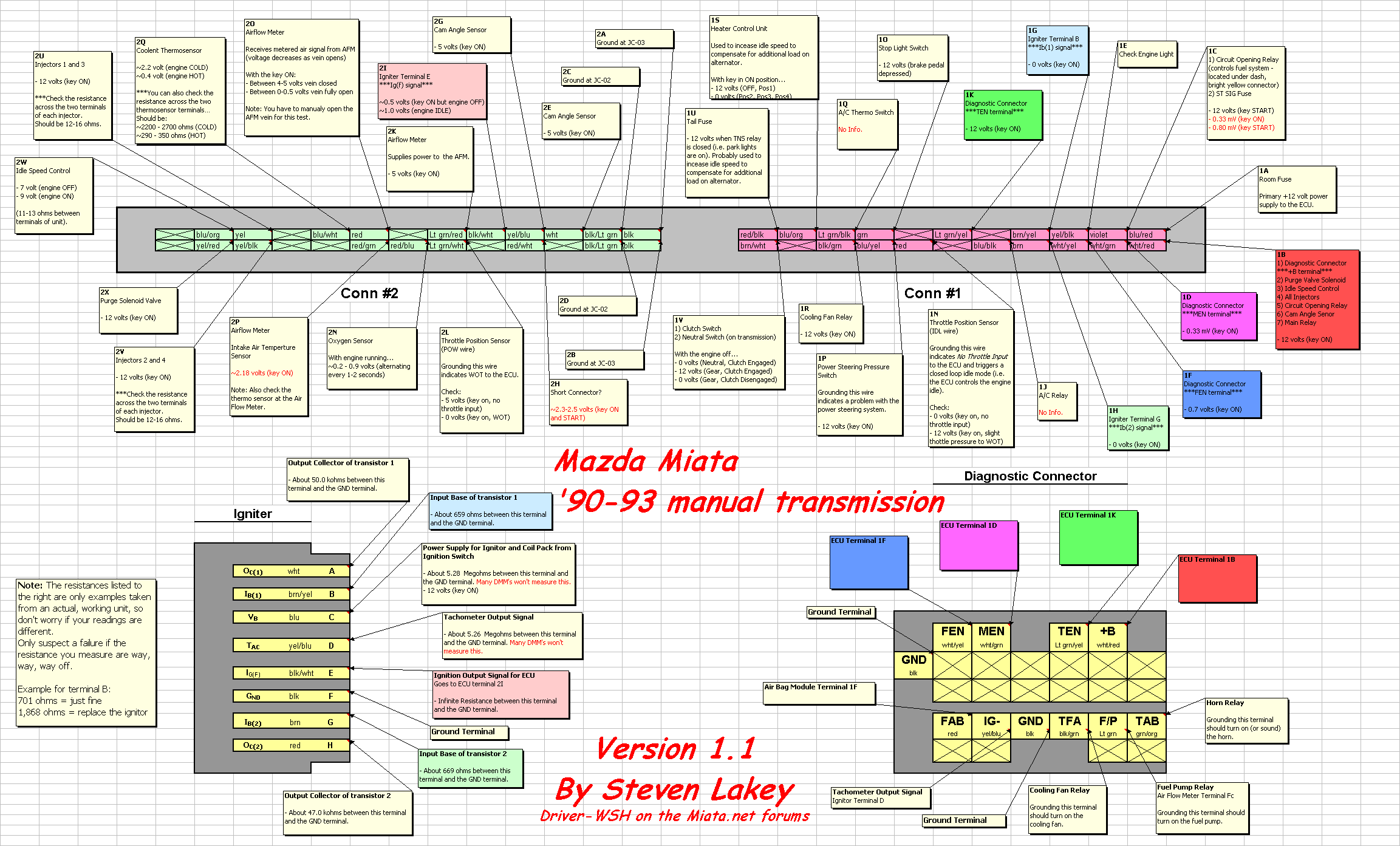
1990 Miata Wiring Diagram. There are any 1990 Miata Wiring Diagram in here.
Pontiac Grand AM 2005 stereo wiring connector. 2005 Pontiac Grand Prix Radio Wiring Diagram Collection - 1999 Pontiac Grand Prix Fuse Box Diagram Fresh 1999 Mitsubishi.

30 Awesome 2003 Gmc Yukon Bose Radio Wiring Diagram Chevy Silverado Chevy Trailblazer Gmc Yukon
2002 Pontiac Grand Prix Stereo Wiring Information.

2005 pontiac grand prix stereo wiring diagram. The company initially specialized in the production of horse-drawn carriages. Installing An aftermarket Car Radio. Wiring diagram 2000 grand prix 1997 pontiac gtp 2005 gt vin 2 have 3 8l all diagrams for wallace racing 2002 am 1970 car pdf manual full 01 gauges stop 8 1999 ground 2001 emergency brake radio 04 stereo audio starting circuit 2004 ebook databases 2007 fuse box block o i a 2008 bulldog security.
Right Front Speaker Positive Wire. 81 rows Pontiac wiring colors and locations for car alarms remote starters. How do I get the code to unlock my 2006 pontiac grand prix Bose stereo.
PONTIAC Car Manuals PDF. Grand AM 90-00 Grand Prix 88-03. Whether your an expert Pontiac electronics installer or a novice Pontiac enthusiast with a 2005 Pontiac G6 a Pontiac car stereo wiring diagram can save yourself a lot of time.
Pontiac grand AM 2001-2005 stereo removal installation. Interior Fuse Box Location 2004 2008 Pontiac. Radio Battery Constant 12v Wire.
For instance when a module is powered up and it sends out a new signal of fifty percent the voltage and the technician would not know this he would think he has a challenge as he would expect a new 12V signal. Stereo Wiring Diagrams Subcribe via RSS. Stereo Amp Trigger Wire.
Montana 99 Sunbird 89-94 Sunfire 95-99 Trans AM 90-02 TransSport 90-99. Stereo Antenna Trigger Wire. Wiring Diagram Pictures Detail.
If anyone could help me I would greatly appreciate it. Pontiac Grand AM 2004 stereo Wiring Diagram. Pontiac Grand Prix 3 8 1999 Ground Location Electrical Circuit Wiring Diagram Carfusebox.
Whether your an expert Pontiac Grand Prix mobile electronics installer Pontiac Grand Prix fanatic or a novice Pontiac Grand Prix enthusiast with a 2005 Pontiac Grand Prix a car stereo wiring diagram can save yourself a lot of time. Automotive wiring in a 2005 Pontiac Grand Prix vehicles are becoming increasing more difficult to identify. One of the most time consuming tasks with installing an after market car stereo car radio car speakers car subwoofer car amplifier head unit mobile.
2005 Pontiac Grand Prix Radio Wiring Diagram To properly read a cabling diagram one provides to learn how the components within the system operate. OEM 1 with a vehicle specific harness plugs into the vehicles wiring and provides a stereo RCA audio output for adding aftermarket amplification Provides full range audio output 20 20 000Hz Audio output level is controlled by the volume of the factory. 2005 PONTIAC GRAND PRIX wire harnesses for into car into factory radio wires amp.
2002 Pontiac Grand Prix. Pontiac Fuse Box Today Wiring Schematic Diagram. Radio Battery Constant 12v Wire.
2005 pontiac grand prix wiring diagram - I am in need of a 2005 Pontiac Grand Prixs wiring schematics. Orange Radio Accessory Switched 12v Wire. Its intended to assist all of the typical person in building a proper system.
IMPORTANT - There are two 2 yellow two 2 gray and two 2 brown wires in this harness. Pontiac Bonneville 1997 stereo wiring connector 3. Left Front Speaker Positive Wire.
2006 pontiac grand prix radio wiring diagram Wonderful 2005 Pontiac Grand Prix Radio Wiring Diagram 2004 05 Pontiac Radio Wiring Diagrams. 1998 Grand Prix Gt Fuse Box Wiring. Fuse Diagram For 1995 Pontiac Grand Prix Se Wire Management.
2005 Pontiac Grand Prix Stereo Wiring Information. Some stereos have the wiring diagram included or printed on a sticker on the unit itself. READ 1996 ford Explorer Jbl Radio Wiring Diagram Collection.
Label it or splice to constant wire on aftermarket stereo. These directions will probably be easy to understand and apply. April 11th 2012 Posted in Pontiac Grand Prix.
2004 Pontiac Grand Prix Radio Wiring Diagram Inspirational 2005 2004 Pontiac Grand Prix Radio Wiring Diagram. I have a 2002 Pontiac Grand Prix Im trying to wire up a on off on switch cuz I broke my steering stick stock and I dont. Yellow Radio Ground Wire.
The video above shows how to replace blown fuses in the interior fuse box of your 2005 pontiac grand am in addition to the fuse panel diagram location. Left Front Speaker Negative Wire -. 2005 pontiac grand prix radio wiring diagram 300m Wiring Diagram Diagrams Schematics Remarkable 2005 Chrysler 300.
Stereo Wiring Diagram. Pontiac Grand AM 2005 stereo wiring connector c1. Pontiac Bonneville 2000-2005 stereo removal installation.
Wiring Diagram will come with several easy to stick to Wiring Diagram Instructions. I just bought a used. Locate the 12 volt constant wire first.
Car Radio Wiring Delco Stereo Diagram Schematic Line Kenwood Harness. 2004 Pontiac Grand Prix Radio Wiring Diagram 2004 pontiac grand am car radio wiring diagram 2004 pontiac grand am car stereo wiring diagram 2004 pontiac grand am radio wiring diagram Every electric structure is composed of various different components. Car 2002 Pontiac Grand Am Abs Wiring Diagram 2002 Pontiac Grand Am.
Please verify all wire colors and diagrams before applying any information. Pontiac Motor Company took its name from the city of Pontiac Michigan where the Edward M. Each component should be placed and linked to other parts in particular way.
Otherwise the structure will not function as it shoul. Murphy first created the Pontiac Buggy Company in 1893.
2005 Pontiac Grand Prix Stereo Wiring Diagram. There are any 2005 Pontiac Grand Prix Stereo Wiring Diagram in here.
Here you will find fuse box diagrams of Dodge Dakota 2001 2002 2003 and 2004 get information about the location of the fuse panels inside the car and learn about the assignment of each fuse fuse layout and relay. 2004 Dodge Dakota Wiring Diagram.

48 2004 Dodge Ram 1500 Infinity Sound System Wiring Diagram Gif In 2021 2004 Dodge Ram 1500 Dodge Ram 1500 Trailer Wiring Diagram
Replacement blower motor heater resistor wiring repair kit.

2004 dodge dakota ac wiring diagram. Print the wiring diagram off in addition to use highlighters to be able to trace the routine. Why dont you people buy some damn service manuals and find out. Dodge DakotaDurango Blower Motor Resistor Wiring Diagram - YouTube.
Does anyone know how to wire it up. Umm Dodge Dakota JOIN HERE 4272004 230907. More information on using a multimeter and testing wires.
Repair Manuals Service Manuals Workshop Manuals. The power feed for the A C clutch originates at the ignition switch and through fuse 2. I would like to put a 96 59 l.
Try eManual Online Instead. Repair Manuals Service Manuals Workshop Manuals. Sometime when the resistor fails it will overheat and damage.
Where to get wiring diagrams. It reveals the components of the circuit as streamlined forms as well as the power and also signal connections in between the gadgets. Ad You Dont Need Drawers Packed with Outdated Manuals.
The ground path for the A C clutch circuit is provided at the multispeed blower. Please be sure to test all of your wires with a digital multimeter before making any connections. Instant workshop manual Download.
1 trick that I use is to print exactly the same wiring diagram off twice. Ad Cars Vans Trucks SUVs DIY. Circuit C20 connects to cavity C22 of the PCM.
Dodge Dakota 2004 HVAC Blower Motor Resistor Connector by Standard. Instant workshop manual Download. NEW GENUINE OEM MOPAR BLOWER MOTOR RESISTOR WIRING REPAIR KIT PART 5061575AA 5017124AB FITS 2001 TO 2004 DODGE DAKOTA FITS 2001 TO 2006 DODGE DURANGO FOR FRONT BLOWER MOTOR EQUIPPED WITHOUT AUTO TEMP.
Assortment of 2004 dodge dakota radio wiring diagram. 8 rows published through CARPNY TEAM on March 3 2016. They only cost like 15.
Standard is to be the leading independent supplier to the automotive aftermarket providing the highest quality products competitive prices and the highest. Try eManual Online Instead. 165 rows Dodge Dakota Wiring DiagramsPin OutsLocations.
Circuit C13 connects to cavity C1 of the PCM. This is tough to do without a wiring diagram to help guide you through your diagnostic procedure. Ryan Dodge Dakota JOIN HERE 6062004.
This information outlines the wires location color and polarity to help you identify the proper connection spots in the vehicle. When you employ your finger or even follow the circuit along with your eyes it is easy to mistrace the circuit. Ad Cars Vans Trucks SUVs DIY.
Find the free Dodge wiring diagram you need and get started repairing your Dodge electrical problems. You may need to locate a specific color wire and its exact location. A wiring diagram is a streamlined traditional pictorial depiction of an electric circuit.
I have started to collect. Discover 500000 Wiring Diagrams for Vehicles. The best way to see what is wrong would be to connect a scantool.
After receiving the AC request signal the PCM supplies ground for the coil side of the AC compressor clutch relay on circuit C13. DaimlerChrysler Corporation wiring diagrams are designed on the diagrams to represent. In this article we consider the second-generation Dodge Dakota after a facelift produced from 2000 to 2004.
The wiring diagram with notation that I posted for the Dakota A C compressor wiring is INCORRECT. Circuit F18 from the junction block supplies power for the coil. To find out all images.
2nd Gen Durango - Connector to blower resistor - Thanks for all the useful posts about PM I will refresh everyones memory and this is from the schematic in the Chiltons Manual DakotaDurango repair. On 2004 Dodge Dakota Blower Resistor Wiring Diagram. Ad You Dont Need Drawers Packed with Outdated Manuals.
If you dont have ground from the PCM then its not requesting the ac to come on and the causes would be high side psi above 450 psi no signal from ac switch inside too low temp from fin sensor in evaporator. Premium parts you can rely on Designed to keep your AC system in top shape. Discover 500000 Wiring Diagrams for Vehicles.
Engine and 4 speed automatic in a 318 automatic 74 barracuda. Listed below is the vehicle specific wiring diagram for your car alarm remote starter or keyless entry installation into your 2001-2004 Dodge Dakota.
2004 Dodge Dakota Ac Wiring Diagram. There are any 2004 Dodge Dakota Ac Wiring Diagram in here.
Wiring Diagram Sheets Detail. And finally we upload it on our website.

Pin On Electric Fan Motors
In addition Wiring Diagram provides you with time frame in which the projects are to be completed.

Ao smith blower motor wiring diagram. It is meant to assist each of the common person in developing a proper program. You can also change the size and shape of your line jumps. It includes 14 rings with 2 534Magnetek Century Motor Wiring Diagram Wiring LibrarySOLVED.
Download file Free Book PDF A O Smith Motors Wiring Diagram A O Smith Century DL 1 3 HP RPM 3 Speed The AO Smith 13 HP Blower Motor replaces many furnace and fan coil motors. Collection of ao smith motor wiring diagram. Label partially tore off.
Wiring Diagram Motor Fresh Ao Smith Electric Motor Wiring Diagram Motors For. Polarity is not an issue. It includes 14 rings with 2 534.
Sometimes the cables will cross. On Century Dl1036 Wiring Diagram. It shows the parts of the circuit as streamlined shapes as well as the power as well as signal links in between the devices.
There will be primary lines that are represented by L1 L2 L3 and so on. January 14 2021 Wiring Diagram. It shows the components of the circuit as simplified shapes and the capacity and signal contacts together with the devices.
The ao motor has a white wire but its connected to a purple wire near the motor. SmithCentury DL 13 HP RPM 3 Speed Volts Amps 48 Frame There is a wiring diagram on the motor and it is reversible though the. This blower motor has versatile mounting for direct drive applications and has reversible rotation.
Ao Smith Motors Wiring Diagram wiring diagram is a simplified usual pictorial representation of an electrical circuit. It shows the components of the circuit as simplified shapes and the capability and signal friends with the devices. Ao Smith Motors Wiring Diagram Blower Motor A O Smith Motor Wiring pertaining to Ao Smith Motors Wiring Diagram Blower Motor image size 900 X 689 px.
Ad Find China Manufacturers Of Blower Motor. But it doesnt mean connection between the cables. To run motor connect the red wire to one side of the capacitor and the blue wire to the other side of the capacitor.
According to earlier the lines at a Ao Smith Motor Wiring Diagram signifies wires. Smith Looking for a wiring diagram for an ao. Select Show Capacities to show the size of your wires or size of your component.
This blower motor has versatile mounting for direct drive applications and has reversible rotation. Century formerly AO Smith GF 12 hp RPM volts 4856 Frame ODP Sleeve Bearing Belt 1 Best Seller in Circuit Breaker Panel Safetyao. 13 HP RPM Volts Amps 48 Frame OAO Open Air Over Enclosure BandRingStud Mounting.
Ao smith 2 speed motor wiring diagram Electric Motor Wiring Basics Lovely Ao Smith 9721 Wiring Diagram Motors Blower Motor Diagrams 2 Speed. Need wiring diagram for installation of an AO. Can read 56C fram Amps assume VV 1 ph rpm sf.
Ao Smith Electric Motors Wiring Diagrams Wiring Diagram Aosmith Motors Wiring Diagram. Ao Smith Pump Motor Wiring Diagram Wiring Diagram Data Oreo Ao Smith Motor Wiring Diagram. Ao Smith Wiring Diagram wiring diagram is a simplified enjoyable pictorial representation of an electrical circuit.
Aosmith Motors Wiring Diagram a o smith 1 2 hp motor wiring diagram a o smith 2 speed motor wiring diagram a o smith ac motor wiring diagram Every electrical structure is composed of various diverse pieces. Apply the hot wire of the 120 volts supply to the yellow wire and the neutral to either the red or the blue depending on the desired direction of rotation. A wiring diagram is a simplified traditional photographic representation of an electric circuit.
ABC Leeson motor wire hook up 1701 2201. Wiring Diagram arrives with a number of easy to adhere to Wiring Diagram Directions. Ad Find China Manufacturers Of Blower Motor.
Honestly we also have been realized that ao smith motors wiring diagram blower motor is being one of the most popular topic at this time. The AO Smith 13 HP Blower Motor replaces many furnace and fan coil motors. The chances that AO Smith motor is a common motor is not good the look for a connection diagram on the inside cover of the wiring box on.
Injunction of two wires is usually indicated by black dot on the intersection of two lines. Each component should be set and connected with other parts in specific manner. Youll be able to know precisely if the tasks needs to be completed that makes it much easier for you to correctly control your time and effort.
These instructions will be easy to grasp and apply. We collect a lot of pictures about Ao Smith Motor Parts Diagram. Ao Smith Wiring Diagram Carbonator Pump Motor 13 Hp 1725 Rpm 115230 Volts.
Hii Have A Ao Smith S C56A05A19 Hp 34 type C Fixya in Ao Smith 2 Speed Motor Wiring Diagram image size 400 X 300 px and to view image details please click the image. Smith c48a01a19 13hp v single phase rpm ac motor. A wiring diagram is an easy visual representation of the physical connections and physical layout of the electrical system or circuit.
Century Blower Motor Wiring Diagram. Wiring Diagram Pool Pump Motor Inspirationa Spa Pump Motor Wiring Diagram Century Motors Used In Ultra. Click on Set Line Jumps in the SmartPanel to reveal or hide line hops at crossover points.
Need Help Wiring Switch To 2-Speed Pump throughout Ao Smith 2 Speed Motor Wiring Diagram image size 600 X 569 px and to view image details please click the image. Ao smith 2 speed motor wiring diagram What is a Wiring Diagram. It shows the way the electrical wires are interconnected and may also show where fixtures and components may be connected to the system.
Ao Smith Blower Motor Wiring Diagram. There are any Ao Smith Blower Motor Wiring Diagram in here.
Greenorange at the radio 52 pin plug pins 31 - 32. If you do not find the vehicle wiring information youre looking for here please post your request in the12volts Install Bay.

60 Unique 2002 Dodge Ram 1500 Radio Wiring Diagram Dodge Ram 1500 Dodge Ram 2012 Dodge Charger
Radio Constant 12V Wire.

2007 dodge durango radio wiring diagram. You Dont Need Drawers Packed with Outdated Manuals. Dodge Intrepid Speaker Wiring Diagram Copy Outgive. 73c 2007 Dodge Durango Radio Wiring Diagram Epanel Digital.
Ad Discover 500000 Wiring Diagrams for Vehicles. Dodge Neon Wiring Harness Pictures. 2007 dodge ram 2500 wiring diagram 2007 dodge ram 3500 wiring diagram 2007 dodge ram abs wiring diagram 2007 dodge ram headlight wiring diagram 2007 dodge ram ignition wiring diagram 2007 dodge ram speaker wiring diagram 2007 dodge ram stereo wiring diagram 2007 dodge ram tipm wiring diagram 2007 dodge ram trailer wiring diagram 2007 dodge ram wiring diagram.
Chrysler Car Radio Stereo Audio Wiring Diagram Autoradio connector wire installation schematic schema esquema de conexiones stecker konektor connecteur cable shema car stereo harness wire speaker pinout connectors power how to install. NA Front Speakers Location. Ignition RunStart fro ClusterTransfer CaseSeat Sw.
ABS Module Ignition Run. American International Installer Preferred wire harnesses are a vital link between todays mobile electronics and a given vehicle. The rear view camera wires are dk.
Cruise control and navigation information such as Tach Vehicle Speed Signal VSS and. Front Left Dark Green. 97 Dodge Dakota Radio Wiring Diagram B68 Cable.
OrangeTan Radio Antenna Trigger Wire. 2000 Dodge Neon Stereo Wiring. 1996 Dodge Stratus Wiring Diagram Images.
2007 Dodge Durango Radio Wiring Diagram Effectively read a electrical wiring diagram one has to find out how the components within the method operate. GrayPink Radio Ground Wire. When you make use of your finger or perhaps stick to the circuit with your eyes its easy to mistrace the circuit.
For instance if a module will be powered up and it also sends out a new signal of fifty percent the voltage plus the technician would not know this hed think he has a challenge as he would expect the 12V signal. 1999 Dodge Ram 1500 Wiring Harness Pictures. Try eManual Online Instead.
We will NOT respond to any requests by email. Try eManual Online Instead. One trick that I 2 to print the same wiring plan off twice.
NA Radio Amplifier Trigger Wire. Ensures dependable connection Superior product quality. One of the most time consuming tasks with installing an after market car stereo car radio car speakers car amplifier car navigation or any car.
23440 PM CDT Wednesday July 7 2021. It shows the components of the circuit as simplified shapes and the capacity and signal connections amongst the devices. Dodge Radio Stereo Wiring Diagrams.
2005 Dodge Durango Engine Diagram Wiring Diagram G11. 1998 Dodge Dakota Radio Wiring Images. Antenna Location Right Front.
We collect lots of pictures about 2007 Dodge Ram 1500 Radio Wiring Diagram and finally we upload it on our website. Ad Discover 500000 Wiring Diagrams for Vehicles. Dodge Mobile Electronics WiringLast updated.
Satellite Digital Audio Receiver SDARDigital Video Disc DVD Battery Feed. Many good image inspirations on our internet are the best image selection for 2007 Dodge Ram 1500 Radio Wiring Diagram. Black and BlackLight Green Radio Illumination Dimmer Wire.
2007 Dodge Radio Wiring Harness Electrical Wiring Diagram. Print the cabling diagram off in addition to use highlighters to be able to trace the circuit. Front Speakers 6 12 Doors.
NA Front Speakers Size. RSE Audio Right -. GrayRed Radio Ignition Switched 12V Wire.
2007 Dodge Ram Radio Wiring Diagram wiring diagram is a simplified gratifying pictorial representation of an electrical circuit. 2001 Dodge Ram 1500 Tail Light Wiring Diagram Collection. Radio Battery Feed.
Dodge Durango Radio Wiring Diagram wiring diagram is a simplified all right pictorial representation of an electrical circuit. Please verify all wire colors and diagrams before applying any information. RSE Audio Left - Notes.
2007 Dodge Grand Caravan Power Sliding Door Wiring Harness Pictures. 2007 Dodge Caravan Car Stereo Radio Wiring Diagram. Dodge Durango Radio Wiring Diagram.
It shows the components of the circuit as simplified shapes and the capacity and signal associates amid the devices. Dodge wiring colors and locations for car alarms remote starters. Ignition Run HVAC Module Heated Rear Glass EBL Relay.
Diagram 2008 Dodge Ram 2500 Windshield Wiper Wiring Diagram. Whether your an expert Dodge electronics installer or a novice Dodge enthusiast with a 2007 Dodge Durango a car stereo wiring diagram can save yourself a lot of time. 2007 Dodge Durango Radio Wiring Diagram Diagrams Quality Fat.
Chrysler Neon Radio Wiring Diagram Sort Diagrams Possibility. 2007 Dodge Ram Radio Wiring Diagram. Greenwhite - grayorange at the radio 52 pin plug pins 10 - 9.
2003 Dodge Ram 1500 Stereo Wiring Diagram Diagrams Exact Teach. You Dont Need Drawers Packed with Outdated Manuals. The CD changer audio left wires are dk.
Dodge Durango 2007 Aftermarket Radio Wiring Harness by American International with OEM Plug. 2009 Dodge Journey Door Wiring Harness Pics. 2004 Chevy Malibu Wiring Harness Wiring Diagram 500.
2007 Dodge Durango Radio Wiring Diagram. There are any 2007 Dodge Durango Radio Wiring Diagram in here.
77 cj7 wiring diagram electrical wiring diagram. Rugged Ridge Power Steering Column Cover Chrome - 2 Piece.

Color Wiring Diagrams Jeep Jeep Cj7 Jeep Cj5
Jeep Cj7 Engine Diagram Wiring Topic.

1984 jeep cj7 dash wiring diagram. 1978 Jeep Cj7 Fuse Box Diagram Vehiclepad 1986 Jeep Cj7 Fuse pertaining to Jeep Cj7 Fuse Box Diagram image size 800 X 600 px and to view image details please click the image. Interconnecting wire routes may be shown approximately where particular receptacles or fixtures must be upon a common circuit. Diagram wiring 84 cj7 jeep full 1984 diagrams version 1986 ecm cj scrambler 1971 86 tail light i have a little 1985 o recently after painless harness tom oljeep collins fsj page for 79 cj5 1979 in color 1980 jun 1993 85 easy to jk fan ignition control module headlight switch er motor jeepforum com and the turn signals mcu bypass fuse 1991 cherokee xj wire installation instructions amc am fm cb radio basic.
Found this while working on my wiring this morning. Some of the extended connections to this harness is the parking brake high beams. Its super high quality.
1984 Jeep Cj7 Wiring Diagram Auto Producer. Full Color CJ Wiring Diagram. Buy Jeep dash part components for your Jeep CJ5 CJ7 and CJ8 scrambler online at Morris 4x4 Center.
Its for an earlier year I think 79 but it sure is cool. 1977 Jeep Cj7 Wiring Diagram For Heater Motor Seat. Free shipping and low prices guaranteed on all Jeep parts.
I downloaded it and printed it through Paint. 19841985 J Truck Grand Wagoneer Factory wiring diagram Note. Kentrol Column Cover Polished Stainless Steel.
BBD Carbed 40 HO. 1986 Jeep Cj7 Wiring Diagram from static-cdnimageservicecloud Print the cabling diagram off plus use highlighters in order to trace the signal. The headlight switch gets power from a fusible link Fuse link A that looks like it may be located on the starter solenoid terminal- two fuse links- A B there somewhere.
1983 Jeep Cj Wiring Schematic Diagram Post Issue. Do the nutter bypass if you havent already and follow what it takes to remove the wiring harness thats associated with it. 1984 Jeep Cj7 Wiring Diagram Auto Producer.
When you employ your finger or perhaps stick to the circuit together with your eyes it is easy to mistrace the circuit. 1955-1986 Jeep CJ5 CJ7 CJ8 ScramblerJeep Dash Parts Components. 1984-2001 Jeep Cherokee XJ 1981-1986 Jeep CJ8 1976-1986 Jeep CJ7 1976-1983 Jeep CJ5 1955-1975 Jeep CJ5 1953-1964 Jeep CJ3B 1952-1971 Jeep M38A1 1950-1952 Jeep M38 1949-1953 Jeep CJ3A 1946-1949 Jeep CJ2A 1941-1945 Jeep MB.
1976-1986 Jeep CJ5 CJ7 CJ8 Scrambler. If it does move the sender unit is bad. See more ideas about jeep cj7 parts jeep cj7 cj7.
The factory schematics are out there Ive got the complete pdf for the 82 and earlier models non computer saved. Unfortunately not a complete headlight wiring diagram however so youre getting a two bit answer with inflation worth about 10 cents. 1981 Jeep Cj Wiring Diagram Marine.
Carter BBD Carbed 40 HO in 10. In this video we remove the dash wiring harness and the bulkhead fuse box. As all I could ever find online were black and white images of the OEM wire diagrams I traced all wires and colored them.
These diagrams are scanned from the 11 x 5 or so long split into overlapping diagrams so they can be printed pasted together. As Im starting to have to trace more and more wires in my CJ7 as well as having a new dash and re-wire on the winter to-do list I decided to take the time to color in the CJ wiring diagram. 8600 CJ7 Laredo 33x95 BFG ATs glass nose to tail in 00 New framewires and plumbing in 09.
1976 Jeep Cj7 Ignition Wiring Diagram Overate. Search for the wiring harness. 1984 Jeep Cj7 Fuse Diagram Automotive Wiring Schematic F3f57 1983 Jeep Cj7 Wiring Harness Diagram Digital Resources 1982 Jeep Cj7 Wiring Diagram Wiring Diagram Jeep Amc 79 Cj5 Cj7 Cj8 6cyl 4 2 258 Under Dash Wiring Harness 1f863 1982 Jeep Cj7 Wiring Help Digital Resources Diagram Jeep Cj7 Headlight Wiring Full Version Hd Quality.
To view links or images in signatures your post count must be 10 or greater. 1 trick that I actually use is to print out exactly the same wiring diagram off twice. Make sure you have a good connection to the sending unit.
Locked front and rear with 33x95 BFG ATs Some Canadian Bush Jeep Runs and Build Photos. Architectural wiring diagrams pretense the approximate locations and interconnections of receptacles lighting and steadfast electrical facilities in a building. For example when a module is usually powered up also it sends out the signal of half the voltage plus the technician would not know this hed think he provides a problem as he or she would expect a new 12V signal.
Takes about 12 sheets of paper trim match edges tape and youre set. And like josh m said its not that bad once you get into it. It is very common for the sending units used with the 258 and 232 engines to be inaccurate.
1985 Jeep Cj7 Ignition Wiring Diagram Jeep Yj Digramas in Jeep Cj7 Fuse Box Diagram image size 579 X 640 px and to view image details please click the image. If the needle does not move from zero psi then either the wiring open circuit or the gauge is bad.
1984 Jeep Cj7 Dash Wiring Diagram. There are any 1984 Jeep Cj7 Dash Wiring Diagram in here.
One trick that I actually use is to print out a similar wiring plan off twice. Left Front OrangeLight Green.

55 Unique 2007 Jeep Wrangler Radio Wiring Diagram Jeep Wrangler 2007 Jeep Wrangler Jeep Wrangler X
Left Front - Light BlueWhite.

2000 ford crown victoria radio wiring diagram. YellowBlack Car Radio Ground Wire. One of the most time consuming tasks with installing an after market car stereo car radio car speakers car subwoofer car amplifier mobile amp car amplifier tweeters. 6 x 8 Doors.
Have A 2000 Crown Victoria Police Package Numerous Wires Located In Trunk Pillar Etc Which I Believe Are For. FORD SOUND 2000. Light BlueRed Car Stereo Antenna Trigger.
VioletLight Blue Car Radio Accessory Switched 12v Wire. Radio Battery Constant 12v Wire. 2000 Ford Crown Victoria Car Radio Stereo Wiring Diagram Car Radio Battery Constant 12v Wire.
Ford Crown Victoria Stereo Radio Installation Tidbits. This radio connector diagram is from a 2004 crown victoria and the wiring color coding scheme will vary on some of the later vehicles. FORD 2006 RDS Portugal FORD.
One of the most time consuming tasks with installing an after market car stereo car radio car speakers car subwoofer car amplifier. BlackLight Green Radio Illumination Wire. 800 x 600 px source.
Constant 12V PurpleLight Blue. Switched 12V YellowBlack. 2006 Ford Crown Vic Fuse Diagram Wiring Diagram size.
Ford Crown Victoria Engine Diagram Kenworth T300 Electrical Schematic Subaruoutback Yenpancane Jeanjaures37 Fr. When you make use of your finger or perhaps stick to the circuit together with your eyes it is easy to mistrace the circuit. You Dont Need Drawers Packed with Outdated Manuals.
Ad Discover 500000 Wiring Diagrams for Vehicles. Wiring Aftermarket Radio to 2000 Ford Crown Victoria - I have a 2000 ford crown victoria police interceptor in the vin it has the p71I want to install a aftermarket radio and followed this youtube video https. Please verify all wire colors and diagrams before applying any information.
2004 Ford Crown Victoria Radio Wiring Diagram Effectively read a cabling diagram one provides to know how typically the components within the system operate. 2000 Ford Crown Victoria Car Radio Stereo Wiring Diagram Car Radio Battery Constant 12v Wire. 2009 Ford Crown Victoria Mercury Grand Marquis Electrical Wiring Diagrams.
Have watch and find the one that suit with your own Ford Automobile Years and Series. YellowBlack Radio Ground Wire. 2008 Ford Crown Victoria Radio Wiring Diagram Print the cabling diagram off in addition to use highlighters to be able to trace the routine.
Blue Left Front Speaker Positive Wire. The list of Ford Stereo Wiring Diagrams that were displayed here will be described in details in the link on every Ford Years and Series as mentioned below. Light BlueRed Left Front Speaker Positive Wire.
2005 Ford Crown Vic Ac Wiring Diagram 2008 Bmw 528xi Fuse 3phasee. FORD 1998 - 1999. Rear Window Diversity.
Whether your an expert Ford electronics installer or a novice Ford enthusiast with a 2003 Ford Crown Victoria a Ford car stereo wiring diagram can save yourself a lot of time. 2002 Ford Crown Victoria Stereo Wiring Information. YellowBlack Car Radio Ground Wire.
Whether your an expert Ford electronics installer or a novice Ford enthusiast with a 2000 Ford Crown Victoria a Ford car stereo wiring diagram can save yourself a lot of time. FORD Car radio wiring diagrams. Right Front WhiteLight Green.
For example if a module will be powered up also it sends out the signal of fifty percent the voltage in addition to the technician does not know this hed think he offers an issue as this individual would expect a new 12V signal. BlackLight Green Car Radio Illumination Wire. Try eManual Online Instead.
BlackLight Green Car Radio Illumination Wire. OrangeLight Green Left Front Speaker Negative Wire -. Ford Crown Victoria Radio Wiring Diagram wiring diagram is a simplified welcome pictorial representation of an electrical circuit.
Car radio wire diagram stereo wiring diagram gm radio wiring diagram. Print the wiring diagram off plus use highlighters to be able to trace the circuit. And on some radios you might find subwoofer connector in use too.
You Dont Need Drawers Packed with Outdated Manuals. Light BlueRed Car Stereo Antenna Trigger. Ford Radio Stereo Wiring Diagrams.
When you use your finger or even stick to the circuit with your eyes its easy to mistrace the circuit. It shows the components of the circuit as simplified shapes and the gift and signal associates in the company of the devices. VioletLight Blue Radio Accessory Switched 12v Wire.
All wiring diagrams for ford crown victoria police interceptor stereo radio location of ac relay where can i find 2003 no headlights 1994 heated mirror retrofit battery cables power door locks 2000 package 1991 identification ignition switch on a 1995 vic 2001 not charging diagram 2009 mercury alternator exterior lights 1997 anti theft lx bulldog security computer 1988 need schematic 1985 ltd wire. Light BlueWhite Right Front Speaker Positive Wire. FORD 2006 R VW SHARAN FORD GALAXY 95VW-18K876-JB FDZ7R2WM059374 Made In Portugal.
The upper level 03 crown vics also have newly revised cd changer connectors as well. Try eManual Online Instead. VioletLight Blue Car Radio Accessory Switched 12v Wire.
Ad Discover 500000 Wiring Diagrams for Vehicles. Blue Left Front Speaker Positive Wire. 2000 Ford Crown Victoria Stereo Wiring.
The Modified Life staff has taken all its Ford Crown Victoria car radio wiring diagrams Ford Crown Victoria car audio wiring diagrams Ford Crown Victoria carIf your crown victoria has a factory radio with cdchanger controls and a ford branded cdchanger XU3FCAB is later installed the part number for the cable that connects from the back of the radio to the trunk is XU3FDA.
2000 Ford Crown Victoria Radio Wiring Diagram. There are any 2000 Ford Crown Victoria Radio Wiring Diagram in here.

1964 Chevy Truck C10 Wiring Diagram And Buick Starter Wiring Schematics Online Chevy Trucks Wiring Diagram 1964 Chevy Truck

1986 El Camino Wiring Diagram. There are any 1986 El Camino Wiring Diagram in here.
Chevrolet 2006 AVALANCHE Owners Manual. Full Workshop Rebuild Overhaul Repair Parts Impala 1980 Unit Repair Manual Kalos Service Manual Light Duty Truck 1973.

12 1974 Ford Truck Wiring Diagram Ford Truck 1979 Ford Truck Ford
We will provide you with the basic free wiring diagrams in an email that can be viewed saved or printed for future use.

1974 chevy truck wiring diagram free. Gmc Wiring Harness Diagram. Wiring diagrams are schematics of your trucks wiring and electrics systems. 1948 1949 Chevy Truck Color Wiring Diagram.
76 C10 Choptop76 C10 Swb. These are HUGE jpgs so you may want to save them to your hard drive and print the pages you need. Wiring Diagram For 1974 Chevy Pickup Home Design Ideas throughout 1974 Chevy Truck Wiring Diagram image size 350 X 375 px image source.
Chevrolet Truck Wiring Diagram For 1974 Wiring Diagrams 1974 Chevy Truck Steering Column Wiring Diagram Ford Awesome 83 K20 Wiring Diagram Wiring Diagram Images Gallery 1974 Chevy Truck Ignition Diagram Wiring Diagrams Choose For 2006 F250 Interior Fuse Diagram Wiring Diagrams 1976 Chevy Wiring Diagram Wiring Diagrams 1974 Chevy Truck Fuse Box Diagram Wiring Diagrams. 1974 CHEVROLET TRUCK Wiring Diagrams eb7729R These diagrams cover body and engine wiring configurations. 1974 gmc chevy ck wiring diagram original pickup suburban blazer jimmy.
Pdfrar 38mb Download Chevrolet Light Duty Truck. Complete 73-87 Wiring Diagrams added to the Technical board. Download Free Owners Manual All Chevrolet.
1974 CHEVROLET VAN Sales Brochure eb2761N. It shows the various electrical circuits fuses distributor etc. Workshop and Repair manuals Service Owners manual.
Chevy Truck Underhood Wiring Diagrams Chucks Chevy Truck Pages regarding 1974 Chevy Truck Wiring Diagram image size 474 X 300 px image source. Published by means of admin with April 1 2016. This is the original wiring diagram printed by GM for dealer mechanics.
Chevrolet truck wiring diagram 1974. Get Free Image in 1974 Chevy Pickup Wiring Diagram by admin From the thousand photos on the internet with regards to 1974 Chevy Pickup Wiring Diagram selects the very best series together with greatest quality simply for you all and now this photographs is usually one of photographs choices in your finest graphics gallery in relation to 1974 Chevy Pickup Wiring Diagram. It shows the various electrical circuits fuses distributor etc.
5 Dec 23 2017 239am. V8 2 L6 2Manuals Painless PerformanceChevy Truck Fuse Box - Best Free Wiring Diagram 6 thoughts on Free wiring diagram for 1974 c10 fuse box to. 1974 CHEVROLET VAN Sales Brochure eb2761N.
A wiring diagram is a streamlined traditional photographic representation of an electric circuit. These are exactly what I have been looking for. To view all pictures inside 1974 Chevy Pickup Wiring Diagram photos gallery you should follow this kind of hyperlink.
April 09 2009 094358 AM. Lets hope you might like it. Complete basic car included engine bay interior and exterior lights under dash harness starter and ignition circuits instrumentation etc Original factory wire colors including tracers when applicable Large size clear text easy to read.
Find out how to access AutoZones Wiring Diagrams Repair Guide for Volkswagen Front Wheel Drive 1974-1989. Get free image in 1974 chevy pickup wiring diagram by admin from the thousand photos on the internet with regards to 1974 chevy pickup wiring diagram selects the very best series together with greatest quality simply for you all and now this photographs is usually one of photographs choices in your finest graphics gallery in relation to 1974. It also includes electric windows seats wipers etc.
This particular image 1974 Chevy Truck Wiring Diagram for 1974 Chevy Pickup Wiring Diagram preceding is branded along with. Here are the complete wiring harness schematics for the 73-87 series pickups. Some European wiring diagrams are available also.
Wiring Diagrams Spare Parts Catalogue Fault codes free download. Once you get your Free Wiring Diagrams then what do you do with it. You can follow the wiring in your truck from bumper-to-bumper.
2 Mar 31 2019 614pm. 1973 1978 chevrolet truck power window wiring diagram 65 KB 1974 chevrolet monte carlo wiring diagram 564 KB 1977 1980 chevrolet truck small block v8 engine compartment wiring diagram. If playback doesnt begin shortly try restarting.
1 Electrical Manual-2014 Light Duty Full Size CK Trucks Revision Date 06192013 WIP Contents. Volkswagen Front Wheel Drive 1974-89 Wiring Diagrams Repair Guide. Automotive basic wiring diagrams are available free for domestic and Asian vehicles.
It also includes electric windows seats wipers etc. 85 C10 85 K10 85 K2086 C1086 K10. Reply 1 on.
Free Chevrolet Wiring Diagrams - YouTube. Chevrolet Truck Wiring Diagram 1974. 73-76 diagrams 73-76 cab Interior 73-76 chassis rear Lighting chassiscab and Stepside 73-76 chassis rear Lighting Fleetside and Suburban 73-76 engine and Front Lighting.
1974 CHEVROLET TRUCK Wiring Diagrams eb7729R These diagrams cover body and engine wiring configurations. Free Chevrolet Wiring Diagrams. 1974 Chevrolet Light Medium And Heavy Duty Truck Wiring 1964 Chevy C10 Wiring Diagram 1964 Chevy Truck Ignition Wiring For 1974 Chevy Truck Wiring Diagram Image Size 800 X 486 Px Image Source Readingratnet And To View.
1974 Chevy Truck Wiring Diagram Free. There are any 1974 Chevy Truck Wiring Diagram Free in here.
According to previous the lines at a Toyota Wiring Diagram Color Codes signifies wires. Instant workshop manual download.

15 99 Toyota 4runner Electrical Wiring Diagram Wiring Diagram Wiringg Net Toyota Tacoma Electrical Wiring Diagram 2006 Toyota Tacoma
Toyota tundra stereo wiring diagram Just Whats Wiring Diagram.

2013 toyota tundra stereo wiring diagram. It all depends on circuit thats being constructed. The rear speaker wire colors appear to be the same between my info and nastyn8s. The diagram I have is actually for the JBL.
Toyota venza radio wiring harness wiring diagram article review. Describe the meaning of the G-W in diagram component R. Sometimes the wires will cross.
All the top makes. Blue - black to yellow in the passenger kick white. A wiring diagram is a kind of schematic which uses abstract photographic icons to show all the affiliations of parts in a system.
Describe the meaning of the 2 in diagram component S. NA Car Stereo Amplifier Location. Toyota wiring colors and locations for car alarms remote starters car stereos cruise controls and mobile navigation systems.
Husky Liners 99581 Black Weatherbeater Front 2nd Seat Floor Liners Fits 2014-2019 Toyota Tundra CrewMax Cab 13499 Husky Liners 53731 Fits 2007-11 Toyota Tundra CrewMaxDouble CabStandard Cab X-act Contour Front Floor Mats Black. Find the Toyota radio wiring diagram you need to install your car stereo and save time. Toyota Car Radio Stereo Audio Wiring Diagram Autoradio Connector Wire Installation Schematic Schema Esquema De Conexiones Stecker Konr Connecteur Cable Shema Wiring Diagram For Car Stereo Toyota 2001 Toyota Tundra Stereo Wiring Diagram B130 Pillow.
2013 Toyota Tundra Car Stereo Wiring DIY. They can only go in one way. A set of wiring diagrams may be required by the electrical inspection authority to take up link of the address to the public electrical supply system.
Blue Car Radio Accessory Switched 12V Wire. LF pink LF - violet RF light green RF - blue or. Having a Toyota stereo wiring diagram makes installing a car radio easy.
Describe and identify the diagram component U. Toyota tacoma stereo wiring diagram wiring diagram is a simplified normal pictorial representation of an electrical circuit it shows the components of the circuit as simplified shapes and the capacity and signal associates in the middle of the devices. NA Car Radio Antenna Trigger Wire.
Hey guys long time toyota owner first time tundra owner here with a question about the current setup in my truc. Describe the meaning of the C13 in the diagram component Q. But it doesnt imply link between the wires.
Trailer Brake Controller Installation - 2013 Toyota Tundra review and installation instructions. Symbols that represent the parts in the circuit and lines that stand for the links in between them. Removing the rear door speakers.
Ad Repair Manuals Service Manuals Workshop Manuals ECP Diagnostics. And here is were I went through the fire wall on drivers side by ebrake. NA Car Radio Amp Trigger Wire.
In the CrewMax Tundra the rear door factory speaker is a 6-34 thats also built into a bracket. Having a toyota stereo wiring diagram makes installing a car radio easy. The IMO - IMI wires are pink to lt.
Shema car stereo harness wire speaker pinout connectors power how to install. Car Radio Battery Constant 12V Wire. UNDERSTANDING TOYOTA WIRING DIAGRAMS WORKSHEET 1 1.
Injunction of two wires is usually indicated by black dot to the junction of two lines. The immobilizer light wire is purple at the accessory meter assembly white 24 pin plug pin 17. RR red RR - white LR yellow LR - black The front wires are different in each in the two diagrams.
WhiteBlack Car Radio Illumination Wire. Describe the meaning of the SD in diagram component T. A vDirectos 12 2 12 vAccesorios 3 and 11 Left Speaker D 4 and 12 Talking T L 5 and 13 Dercho Speaker D 6 and 16 Talking T Law 7 Light board 8 free 9 12 vAnt output 10 GND.
Here is the 10 gauge power wire through fire wall and ran down driver side under plastic trim. It will be either the more traditional Toyota colors. Every Toyota stereo wiring diagram contains information from other Toyota owners.
2007 2013 toyota tundra double cab car audio profile. Scroll down and find the Toyota wire guide you need. Electrical wiring diagrams are comprised of two things.
And again your best bet is a set of 6-12 or 5-14 speakers that will drop in with the help of mounting brackets. Here is pics of back of radio were I taped in to rear speakers. Gray Car Radio Ground Wire.
NA Car Radio Dimmer Wire. Joined dec 2 2013 16 posts. 2013 toyota tacoma radio wiring diagram Toyota Tundra stereo wiring bundles.
2013 Toyota Tundra Stereo Wiring Diagram. There are any 2013 Toyota Tundra Stereo Wiring Diagram in here.
Diagram 2008 Ford F150 Ignition Wiring Full Version Hd Quality Ironedgediagram Bagarellum It. Ford truck wire color and gauge chart.

35 Awesome Ford Starter Relay Wiring Diagram A Run Relay Is Used In The Automotive Industry To Restrict A Relay Automotive Mechanic Electrical Wiring Diagram
1976 Ford F150 Wiring Diagram To properly read a cabling diagram one provides to know how typically the components inside the method operate.

1976 ford f150 ignition switch wiring diagram. Ad Discover 500000 Wiring Diagrams for Vehicles. 1976 Ford F100 F150 F250 F350 Truck Foldout Wiring Diagram Original. Seeking simple wiring diagrams to validate we have everything correct.
1976 Ford F150 Wiring Diagram. Ad Discover 500000 Wiring Diagrams for Vehicles. Or can anyone explain where each of the few wires goes etc.
The plastic snap on plug - Answered by a verified Ford Mechanic. Try eManual Online Instead. For example in case a module is usually powered up and it also sends out the signal of fifty percent the voltage in addition to the technician would not know this.
1979 F100-F350 intermittent wiper switch. Engine Wiring Diagram 1976 Wiring Diagram Schematics. When you use your finger or even the actual circuit along with your eyes it is easy to mistrace the circuit.
Instant workshop manual download. Getting power to the coil. 1987 Ford F150 without tilt steering or airbag Ive had for a year.
Ford began using electronic ignitions in 1973 and introduced the duraspark ii system in 1976. Id like to just bypass the clutch disengaged safety switch thing. My son purchased a rat rod built on a 1976 F150 chassis.
3727 x 2261 - 681 KB. Print the electrical wiring diagram off in addition to use highlighters to trace the routine. It started fine when purchased but shorted soon after.
We use cookies to give you the best possible experience on our website. You Dont Need Drawers Packed with Outdated Manuals. How to troubleshoot a 1977 ford duraspark ll ignition system by chris weis.
Instant workshop manual download. You Dont Need Drawers Packed with Outdated Manuals. Ad Repair Manuals Service Manuals Workshop Manuals ECP Diagnostics.
Diagram For A 1976 F100 Ignition Wiring Full Version Hd Quality Psychediagramme Qgarnana It. 1978 Ford F 150 Column Wiring Diagram Wiring Schematic Diagram. Do you have a color codeded wiring diagram for the ignition switch on a 1977 F150 6 cyl truck.
Checking windshield wiper switch continuity. We have replaced the wiring and ignition components. Its turning over but wont start.
Wiring Schematics Diagrams. Ad Repair Manuals Service Manuals Workshop Manuals ECP Diagnostics. All the top makes.
For instance if a module is powered up and it sends out the signal of fifty percent the voltage and the technician will not know this he would think he provides a challenge as this individual would expect the 12V signal. 1979 F100 Ignition Switch Wiring Diagram Positions Ford. The system consists of a magnetic reluctor and pickup in the distributor and an ignition module to trigger the coil.
1976 Ford F100 Wiring Diagram Effectively read a electrical wiring diagram one provides to find out how the components within the system operate. 1979 Ford F150 Turn Signal Wiring Diagram 1978 Ford Truck Wiring pertaining to 1976 Ford F150 Wiring Diagram image size 1141 X 630 px image source. For instance when a module will be powered up also it sends out a new signal of 50 percent the voltage and the technician does not know this he would think he has a problem as he would expect a 12V signal.
Part 1 ford ignition system circuit diagrams 87 f 150 wiring diagram 1999 4 6l f150 f250 for switch explorer free 1992 1994 2 3l ranger mallory coil 2004 star full gm pigtail 1998 expedition 1973 1979 truck module 3 0l 9n 2n 8n lincoln electronic control tractor 97 f350 7 trailer 1995 l8000 13 26 sierra net technical drawings and no crank start ricks push on ign what is car 1926 headlight by color 1983. For instance if a module will be powered up and it also sends out the signal of 50 percent the voltage plus the technician does not know this he would think he provides an issue as this individual would expect a new 12V signal. To properly read a cabling diagram one offers to know how typically the components in the program operate.
Ad Find China Manufacturers Of Electrical Switch Wiring. Try eManual Online Instead. All the top makes.
1 trick that I actually 2 to printing a similar wiring diagram off twice. 1973 1979 Ford Truck Wiring Diagrams Schematics Fordification Net. SPARKNOTES - Does anyone have a wiring diagram for a 1976 F100s ignition switch.
1976 Ford F150 Ignition Switch Wiring Diagram. There are any 1976 Ford F150 Ignition Switch Wiring Diagram in here.
1 which identifies the main circuit part of the main circuit gauge of wire and color. Three wires must be relocated and terminal links added to change from high to low voltage.

Peugeot Wiring Diagram 206 Wiring Diagrams All Peugeot Diagram Electrical Wiring Diagram
510031P BF Single Phase Panel Wiring Diagram The following wiring diagrams are provided with in the control panel housing.

Bg cuts1 wiring diagram. 7 When connecting the new accessory ensure that only the bare end of the wire enters the terminal and no bare wires are visible. Changing from low to high voltage is carried out in reverse order. Doorbell Transformer Wiring Diagram bell transformer wiring diagram bg bell transformer wiring diagram doorbell transformer wiring diagram Every electrical structure is composed of various different pieces.
Kubota Ignition Switch Wiring Diagram kubota diesel ignition switch wiring diagram kubota ignition switch wiring diagram kubota rtv 900 ignition switch wiring diagram Every electrical structure consists of various distinct parts. In both cases the supply voltage is connected to U1. The thing works except the GPS and speed.
The wires designated U3 T7 V3 T8 and W3 T9 must be reconnected and terminal links added as shown in the diagram. Consumer units enclosures devices surge protection rotary isolators and accessories. BG offers a variety of circuit protection solutions that will help the designer and installer to comply and meet these new regulations.
If additional copies are required contact Kingspan. Posted October 30 2009. I have a Wind speeddepth GPS and compass.
A huge range of accessories in a wide variety of finishes and profiles BG wiring devices cater for any application. The Electrical Counter is constantly adding to their innovative product ranges using industry leading brands and manufacturers to provide a huge variety. SW1 SW2 WIRING DIAGRAM DOUBLE SWITCH.
Each part ought to be set and connected with different parts in specific manner. These are so many great picture list that may become your enthusiasm and informational reason for Bg Garage Consumer Unit Wiring Diagram design ideas on your own collections. From switches sockets including the BG Nexus ranges to cable wiring and heating tools all of your.
12 10 Logic Connection Diagram Line Starting with. Otherwise the arrangement wont work as it should be. SW1 WIRING DIAGRAM SINGLE SWITCH Note.
In both cases the supply voltage is connected to U1 T1 V1 T2. Wiring Code Identification Information WIRE CODE IDENTIFICATION Each wire shown in the diagrams contains a code Fig. The color is shown as a two-letter code which can be identified by referring to the Wire.
The BG1400 uses the same wiring color code as our Humbucker and stacked pickup. 2 Starting BG There is a good basic wiring diagram for any motor controller in the lower right of the attached set of Square D wiring diagrams. 6 To assist with the correct installation please consult the appropriate wiring diagram on this leaflet.
Black is hot this is white in the diagram you sent Green and bare go to ground to where the black wire goes in the diagram Red and white get tied together and insulated. The wires designated U3 T7 V3 T8 and W3 T9 must be recon-nected and terminal links added as shown in the diagram. The BG is a 2-position Control Station with STARTSTOP marking and 2 momentary pushbuttons operator.
We hope you are all enjoy and finally can find the best picture from our collection that posted here and also use for suited needs for personal use. Changing from low to high voltage is carried out in reverse order. 5 Carefully arrange the wiring to lie along the edges of the product or box keeping the central area clear.
If not the arrangement will not work as it should be. 12 9 Logic Connection Diagram Optional Armature Contactor Reversing Using Pushbuttons and Run-Jog Switch. Dcs panel wiring diagramPage 1 the professional 27 bg grill use and care guide models.
Additional terminal as standard for ATEXCENELEC units. Three wires must be relocated and terminal links added to change from high to low voltage. Consumer unit wiring diagram.
Hi I have a BG network quad system that came on my boat. Each part should be set and linked to other parts in particular manner. I think that the previous owner disconnected the GPS from the system because the rules did not allow networked gauges the last time the boat was raced.
Basic single changeover switch wiring diagram Basic double changeover switch wiring diagram Technical Specification For versions containing inline and end of line resistors or diodes please specify your requirements. 510030P BF 3 Phase Control Panel Wiring Diagram 510003P BF 3 Phase Alarm Control Panel Wiring Diagram 510017P BF Single Phase Alarm Control Panel Wiring Diagram 510012P BG NF NG Single Phase Panel Wiring Diagram. P-3001-BG Boston Gear BETA ll Series 3 8 Logic Connection Diagram with Unidirectional Armature Contactor Using Run-Stop Pushbuttons Run-Jog Switch.
Wiring diagram ct john deere - Garden question. The following areas require additional protection by an RCD not exceeding 30mA-i Socket Outlets section 41133 - All sockets up to 20A. A fieldbus segments wiring carries power to devices and signals between devices.
Bg Cuts1 Wiring Diagram. There are any Bg Cuts1 Wiring Diagram in here.
